Difference Between Circuit Diagram And Schematic
BlogDifference Between Circuit Diagram And Schematic A Stepper Motor Circuit Diagram is a visual representation of the components within a stepper motor and how they interact. It helps to illustrate how current moves around the motor, enabling it to rotate accurately. A circuit diagram can also highlight the different types of connections within the motor, allowing for easier troubleshooting if

And hence, this Stepper Motor Driver Circuit is essentially a Binary Counter Circuit. Stepper Motor. A 12V Stepper Motor is used in this project. It is a Unipolar type Stepper Motor with 5 - wire configuration. Basically, Stepper Motors are classified in to Unipolar Stepper Motors and Bipolar Stepper Motors, based on the windings of the stator.

Master Stepper Motors: DIY Driver Circuit Guide (Easy Build!) Circuit Diagram
Learn how to build a simple stepper motor controller using four transistors, two NOT gates, one XOR gate and diodes. The circuit diagram shows the parts list, the control logic and the power supply for the motor.

Learn how to read and understand the schematic diagram of a stepper motor, an electromechanical device that converts electrical pulses into mechanical movement. Find out the key components, such as power supply, controller, driver, and motor, and the different types of stepper motors, such as bipolar, unipolar, and hybrid. The circuit diagram has a two-stage stepper motor driver. Here the timer IC 555 works as an astable multivibrator to generate a clock or a square wave. And produced a square pulse based on the timing resistor and timing capacitor. The frequency of clock generation, in this case, cannot be kept constant so we need to get a variable speed for the

Driver circuit with circuit design Circuit Diagram
Wiring diagram/schematic for A4988 stepper motor driver with Arduino and stepper motor. The wiring diagram/schematic above shows you how to connect the A4899 driver to a stepper motor and the Arduino. The connections are also given in the following table: A4988 Connections. A4988 Connection; VMOT: 8-35V: GND:
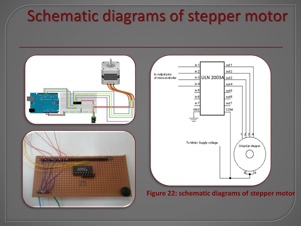
Key learnings: Stepper Motor Driver Definition: A stepper motor driver is defined as a circuit used to drive or run a stepper motor, consisting of a controller, a driver, and motor connections.; Essential Components: Key components include a microcontroller, a driver IC like the ULN2003, and a regulated power supply.; Stepper Motor Controller: The controller must have at least 4 output pins
